The Project

The project "Dream of Flying" is a Zeppelin inspired personal air transportation in the year 2031.

The problem we face now is that we are so limited to this two dimensional transport network, everything is on the same level, sharing the same road with thousands of other people, pushing, squeezing trying to find a way out. There is a simple solution - give people wings to fly.
I believe flying is the next evolution of transportation. We will step into an age when we take all that messy trails of tail lights and set them free into the sky.

Saturday 15 October 2011

Been a while since the last upload. The CAD Model took me forever to make...rhino is very difficult...
But I finally managed to get it close to finish... here is some quick peeks of the model
The gas bag still need a bit of work....


Friday 9 September 2011

New Concept - Cockpit&Main body


In this new concept the passenger part of the airship is very important. It must have the quality of: light, compact, aerodynamic and visually appealing.


Concept1 is the one that appeals to me. The main structure/bones/chassis is a light carbon fibre structure that one piece. The passenger/pilot seat is a part of the chase which will be argonomically designed to fit all drivers. The tripod like landing gear will be another seperate piece, attached to the chassis by shock absorbers for stable landing. The cockpit part will be covered by transparent polycarbonate instead of glass for weight reduction.

Here is the rough clay model of the main chassis, just to give an idea to draw and develop on.

Mockup Prototypes - Configurations


Mockup 1 :
Here is the first mockup prototype for the new concept. It is to scale of 1:50. The wing/gas bag has a dimension of 13m in height, 5m max width and 2m max thickness. Around 100 cubic metres of volume in wing shape or less but should be more than enough to lift the airship.
This configuration has a single vertical structure to hold the gas bag in rotating axis, cord will be used to secure the gas bag to the cockpit and initiate the rotation action. 
The single vertical structure is fragile, but it shouldn't be used to support much weight as the gas bag will be lighter than air, so in reverse the vertical structure is used to hang the cockpit. However other configuration should be tested further.


Mockup 2:
This is the alternative configuration that is more rigit in structure. 2 vertical structure securing the axis.
But the extra structure will add more weight. Also adding complication in folding down the structure for storage.
It certainly looks more secure, rigit and more safe then mockup 1?

Mockup 3: (Photo will be updated later)
Another single vertical structure configuration. The gas bag is devided into 2 parts. located on each side of the axis gives more weight balance than mockup 1.

Sunday 4 September 2011

The Alternative concept

This is a quick sketch of the alternative concept in mind.
The cockpit is a very light structure consisting the seat, interface and the turbine engine. It is attached to a vertical structure which will hold the vertical gas bag in place. The ship transforms in mid air by pulling cables on one side of the gas bag, with the center of axis in the middel it will flip horizontal for gliding motion. The cables are supporting structures to hold the gas bag inplace. The gas will come externally to save weight and space. Then there will be infrastructure needed to inflate and deflate the gas bag.


Unresolved problem 1 - How to deflate and store the gas bag in relation to the gas bag structure. Since it need to be in the right shape of wings it will probable need a rigit structure. Solution in mind "1" is semirigit material that can be folded back, "2" profiles in between the gas bag that devide the gas bag in different section but the tension will hold the gas bag in shape. These profiles can be fabric aswell.

Unresolved problem 2 - How to colleps the vertical structure. Fold and colleps down? Is that going to compramize the rigidity of the structure?

Unresolved problem 3 - the rotation motion. It will need a axis to rotate. How to provide this axis. The rotational motion will be effected by wind and air friction. But the rotation can be utilized to navigate the airship while gliding.

Saturday 3 September 2011

Evaluation?

It has been a while since the last update.

During this time, there were some complication with the concept I have chosen to proceed with. The structure or skeleton that forms the shape I want and the material for the skin cause too much problem. And there was the problem regarding if this shape really gonna fly or not. I think I have been idealizing this concept since I love the aesthetics so much, I grow some attachment to it. I want to see it to be done. It will probably need some imaginary material for this concept to be feasible. So I am going to find an alternative concept. Hopefully this time it will be better.

Monday 22 August 2011

Concept Part3

These are concept renderings explaining the 3 phase of the ship. The ship should be fabricated with a engineered high elastic latex.
Ground mode is a compact vehicle. The outer skin raps around the entire vehicle except the cockpit area which should be enclosed in a hard structure for safety.
The inner skeleton act like structure which can extend to certain size to form the gas bag.
Flying Phase
The flying phase has 2 part, the lifting and gliding. The gas bag will be fully inflated with hydrogen to lift off  and when reach certain height, the inner structure changes shape to form wings to glide.

Friday 19 August 2011

Foam Model Part2


Finishing off the model, the gas bag part and the transformed glider. Still pretty rough. Started to sketch over the photo in PS. Here is 2 of the sketches. Still missing the landing gear and the thrusters. Doing some more sketches on paper later.

Tuesday 16 August 2011

Foam Model Part1

I have decided to move forward and start developing Concept 2 from last post.

Started to create some physical model to visualize the shape.

This is only the main body of the ship in landing phase. This is the hard part of the ship, consisting the cockpit, gas tank? engine and fuel cells. I cut the mid part for components and where the inflated balloon comes up.
This thing look like a UFO or Alien ship... the little wings are stabilizers to the gliding.


Saturday 13 August 2011

Concepts Part2

Developed from the previous concepts, 3 concepts came across my mind. The all have 1 identical feature, that is taking the large volume into the vertical space. This way, the vehicle will remain compact at ground level, not occupying a lot of land space.

Concept marked "1" is a concept driven from concept "2" from the last set. The giant gas bag is utilized as sails like sail boats, utilizing wind as it's power - I like to call them hydrogen sails. The sail split into 2 halves, they close up when the vehicle is going with the wind, the wind can push the vehicle forward, but when the vehicle is going against the wind, the sail split into 2 and became another set of wings.  In this case the wings of the aircraft can be smaller as the gas bag can go as large to satisfy the displacement requirement

Concept Marked "2" is an aircraft made from elastic material like "latex". It remains a small compact vehicle in the ground mode. When taking off, the body of the vehicle inflates with hydrogen, a inner structure is required to hold the vehicle in shape like graph 2. The gas bag can go as high as it requires to take off with the aid of the air ducts under the vehicle. When reached a certain height, the inner structure changes, a set of wings will morph out from the side of the vehicle, a large proportion of volume will be transferred to the wings making the gas bag smaller to minimize the wind and weather impact. I prefer this concept as it is very different and it resembles it's ancestors zeppelins.4

Concept Marked "3" is a aircraft inspired by star wars fighter ships. It has 2 large vertical wings inflated with hydrogen. In the center holding the 2 wings together is the main body of the ship, where containing hydrogen tanks, fuel cells and turbine engine. It also provides propulsion to the ship. The cockpit, for easy access, is hanged on the side of the ship. It consists a gyro to maintain the pilot in the same upright position through out the flight. The wings can deflate and retract into the main body. This idea sound a bit crazy, because it need to land vertical and after take off turn 90 degrees to a gliding position. It is fun to imagine aircraft take off and flip and glide away....

Thursday 11 August 2011

Concepts Part1

This stage of design is not so much about looks, aesthetics or style. It is focusing on solving the design problem: How to design the gas bag so it does not interfere with the flying experience and minimizing landing space requirement.

The initial Package drawing were drawn in Solidworks. Just to establish a basic skeleton to the aircraft, consisting the essential components - hydrogen tanks, fuel cells, turbine engine, seat for 1 person and most important the wing size. The wings will be inflated and take up vertical space as well.
The problem and it is the problem to all lighter than air aircraft - LTAA (even though this is only a semi-lighter than air aircraft) is it's gas bag. All LTAA requires a large amount of displacement to generate enough lift to lift the aircraft.
The idea of this concept is to reshape the gas bag and convert it into lifting surface - wings and turn the aircraft into a glider. In the history of LTAA, all the blimps were basically long cigar like tube shapes, some of them are very well streamlined against the frontal wind, but their extremely large body rendered them vulnerable to extreme weather, heavy cross wind, and making them harder to control and required a lot of power to move forward.
By spreading the volume of the gas bag into a large horizontal surface it can be utilized to generate lift for gliding making it easier to travel long distance and dramatically reduce power consumption, in the mean time making it easier to operate and adept to any weather conditions.

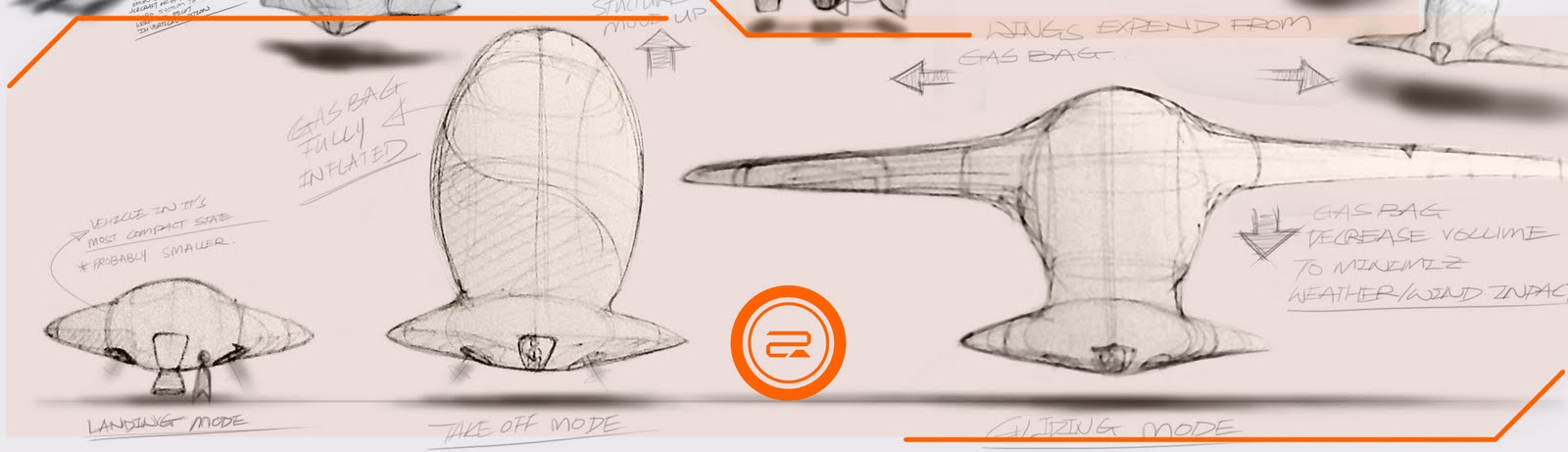
So based on the Package drawings, I started to sketch some ideas, just to play around with the configuration of the wings/gas bag. Trying to find a good configuration of the wing that provides enough volume but also requires less space. The design requirements for the wings are - they have to maintain enough volume for displacement but also maintain the air foil shape.

Concept marked "1" is a bi-wing (double wing) configuration. It is probably the most obvious idea, but it is proven to work. The bi-wing configuration provides good lift but produce more drag than single wing configurations, that is the reason it was render obsolete. With the design requirement of the wings multiple wings seem to be the better choice.

Concept marked "2" is a strange looking aircraft. The idea is simple, if the wings don't provide enough lift, just add an additional gas bag to fill the requirement. Of cause the gas bag on top is going to become a problem with the cross wind and frontal wind, but there is something cool about this aircraft, it is different from all other concepts, and the idea of utilizing vertical space comes to mind....

to be continued.....

Monday 25 July 2011

About test rig - 1

Last semester I did the first test rig. It was a RC helicopter tethered with helium balloons. The test was about the efficiency of the combined lift system. A water bottle is attached to measure the weight change affecting the lift.


This system is proven to work with Zeppelin-NT the German zeppelin that is still in operation today.
http://www.zeppelinflug.de/seiten/E/default.htm

PS. This service can be hired for marriage proposals......contect me for detail

Week2 Day1

Made this on Sunday, it's a "flying wish lantern". Same principle as a hot air balloon.
It didn't work as I expected. Reason being the size was small, the whole thing was too heavy to lift on hot air, and the shape is a little off too. Now I understand why the real one has a larger top and a smaller openning, it is to trap hot air inside. The one I made was straight so the hot air keeps tipping the lantern upside down. The paper I used was a bit too heavy, it needed paper that is very light for example tissue paper or a very thin plastic bag (plastic bag might not be able to with stand the heat).
Overall, I found this test pointless.

Wednesday 20 July 2011

Day4

http://www.flightlearnings.com/airfoil-design-part-1/176/
Learning the basics about airfoild

Day 3

The first step for me is to design and build a test rig to test if the flying blimp is going to work. Gona try to head down to the hobby shop and get some mateirals hopfully some one there can help me a little...

Today I was trying to build a mock up wire frame and cover it with paper to test the aerodynamics, but turns out the wires can't be solder. Need to find proper material!

The road so far (Part3)....

I have decided to go with Concept 3 which has the most potential to become a new type of transporter instead of a upgrade or redesign.

This vehicle might not work (isn't suppose to?) since it is a concept for the future. Viewers, keep in mind that this is a visionary design :) so some part just have to wait for technology to catch up XD.

The theory behind Concept 3 is it utilizes all kind of natural force (that is the reason I like it so much) and they support each other. The whole vehicle is like a glider utilizing gravity and aero-dynamic lift to fly, the airship technology comes in to make the aircraft lighter for longer flying distance and also help it to take off. The only problem with gliders is they need a runway and a force to start with (or it can run off a clift) so I added a hydrogen fuelcell powered turbine engine to give it a kick!(For those of you still think hydrogen is dangerous for the airship, it is flammable but it's not the cause of the desasters. Most of the airships went down because of their size and difficulty in controlling in weather conditions.)

Monday 18 July 2011

The road so far (part 2) .....

These are the 3 concept directions.
This is a concept drived from traditional airships. It has enough volume to carry hydrogen to lift about 3-4 people (a family) The airship has a large surface area, so it will glide like a kite. For propulsion the airship can change it’s density by lowering thehydrogen level, so when it’s heavy gravity will pull it down hense giving it momentum. This momentum will be utilized to drive the airship forward.
This concept is a hybrid of ground vehicle and air transport. A light weight ground vehicle is privately owned by the user and work the same way as an electric car. But if you like to travel long distance or don’t want to get cought in traffic, you can order an air transport survice. There are free airships floating around the city, and you can find a docking area for the airship to pick you up. The airship will pick up the car by mounting themselves to the specially designed wheels. This will be a charged survice.

This concept is the most compact, suited the design schematic the most.  The idea is to create a single person transport “POD” which is compact and easy to use. The vehicle is a hybrid of different systems, it uses hydrogen fuel cell powered turbine engine for thrust and aid lift, the wings are foldable and inflateble with hydrogen to utilize buoyancy to lift the vehicle. The large wing span and aerodynamic shape allows the vehicle to glide in the sky, the turbine thruster will only act as an aid for longer and faster flight. The package of the vhicle should be simple for light weight purpose. 

The road so far....

It's coming to the second and last part of my post graduate study. (1 more semester to go and I am finally done with studying XD)

The project is going well up till now, it has its difficult moments but I am happy to say I managed to pull it off.

Things I have done:
Initial research about the problem, technology and user aspects
Initial concepts showing 3 different concept directions (see part 2)

About Me

My photo
Runaway Prototype Design is a start up design consultancy based in Australia's creative capital Melbourne. Currently operated by industrial design professional/concept artist - Jet Shao a.k.a Runaway Prototype, ceramic artist/product designer - Lucy Liu a.k.a Runaway Bunny. Runaway prototype provide a wide range of design services from graphic design to designing products for everyday use. We develop our own product to suit the market. We also love to work with passionate entrepreneur with a big idea. So if you have a big idea love to see it become reality, don't hesitate to call us. ​

Followers